Lighting calculation is required to achieve a good lighting design and to determine the number of lighting fixtures required for each room/part in your building. Lighting calculation can be done either manual way or using the software.
This post will focus on designing using DIAlux software, I’m using DIAlux 4.13. DIAlux is one of the leading software on lighting design, used to calculate, and visualize indoor/outdoor lights, which is a time-saving software when compared to the manual calculation. Actually, there is much other software you may use, for me, DIAlux was recommended to me by my supervisor during Coop-training. Regarding the manual way is a very simple algebra but in case huge projects it be will more efficient to use software instead.
A lighting design generally begins when the architect or interior designer develops floor plans for a building the below architecture plan.

1- First thing first, create a new project and insert a new room > import the architecture drawing into DIAlux where it can calculate all the required dimensions and there is no need to enter any dimensions manually. Go to file then > import > select DWG or DXF file then Select the file you wish to Import and click Open.

It is important to save the dwg file with the 2010’er format of AutoCAD in order to successfully imported.
2- Click and drag the corners of the New Room to the desired room on the DWG and edit room geometry.
3- Fill in the general information for each room click on the room name > go to the maintenance plan method tab> add Maintenance Factor value, and the room surfaces tab adds the Reflector Factors percentage. Repeat steps 2&3 for all the rooms in your plan.
Lightings performance can be affected and decreased over time due to surrounding factors, such as wear, dust, type of bulb, etc. These factors are accounted for through the inclusion of a maintenance or light loss factor.
There are two important parameters to have the calculations done first one is the Work plan which imaginary plan (about 75 cm) above the floor where most of the usual tasks take place. Wall zone or Boundary zone the calculations can be limited to a certain area inside the room and reduced by a peripheral margin from each wall (about 0.5m).
4- Click on the Luminaire Selection tab >> DIAlux Catalog, there are different lighting manufacturers supported by DIAlux. You will first need to obtain the manufacturer catalog. Click on the manufacturer name, and it will directly open up their website, where you can download and install their catalog.
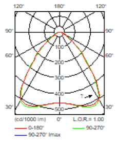
Below is the Philips catalog, one major thing to consider when selecting luminaires is the methods of mounting, indoor or outdoor, protection mode, and light distribution. Light distribution can be represented by Polar Intensity Curves.
- Polar Intensity Curve is the plot that shows the relationship between the Candle Power and Angular Position and provides a visual representation of the light intensity distribution expected from the luminaire.
5- After that, to insert the selected luminaire select the room by right-click > insert luminaires > field arrangement. Through the position tab, it possible to adjust the No. of rows, No. of columns, enter the required lux level. There are recommended lux values for each specific area as per The Illuminating Engineering Society (IES) standard.

Average wall luminances of at least 30 to 100 cd/m2 are preferred in typical office work spaces (where 300 to 1000 lx is provided on the workplane). Read IESNA Lighting Handbook 9th Ed. Illuminating Engineering Society of North America
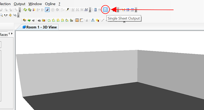
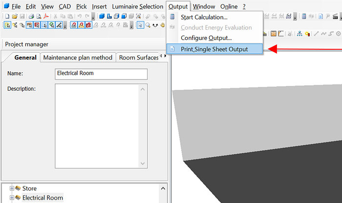
6- Right-click on the room name then calculate > Single sheet output in order to show the calculated result or from the menu bar select output then >print single sheet output as shown below.
Two points that need to be considered in lighting calculations:
- Maintained illuminance is the lighting level on the given area, average, minimum, and maximum (Eavg, Emin, Emax)
- Uniformity Factor (UF) of the lighting, as determined from Eavg/ Emin its value should be close to 0.9/1. The below figure shows the effect of the UF.

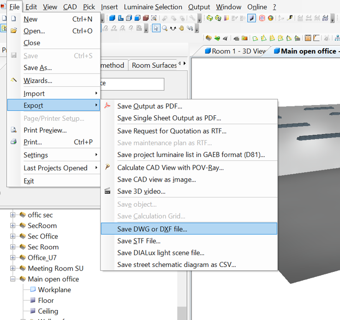
7. Last step! export the file as a cad file in order to prepare the lighting layout, click on file > export > save DWG or DXF file ..
References:
- Dialux Technical support, software help.
- IESNA Lighting Handbook 9th Ed. Illuminating Engineering Society of North America
With this, we come to the end of this article. I would like to thank Eng. Ahmed elsobky for his awesome course on udemy!. If anyone has comments or suggestions on how to improve the post, please add them below or you want to share more information about the topic discussed above, please don’t hesitate to discuss through Gmail or add me on LinkedIn. All the best!